Simple USB Type-C Upgrade for the Raspberry Pi Pico
DIY Today - Future-Proof Tomorrow
With USB type C ports now commonplace, keeping micro-USB cables around for some devices can be a bit of a nuisance. The convenience of a single, reversible cable for nearly all your devices is undeniable, and in some devices the micro-USB port can actually be replaced with a USB type C one… given you aren’t afraid of a little soldering. Before tackling more intricate electronics, let’s start small — a simple mod for the Raspberry Pi Pico the perfect way to get started.
Requirements
This project calls for some essential soldering tools. A soldering iron, sponge, and solder should be enough to get you started. Along with these tools, you’ll need a few additional components:
- a Raspberry Pi Pico
- four pieces of electrical wire (which I salvaged from an old USB cable)
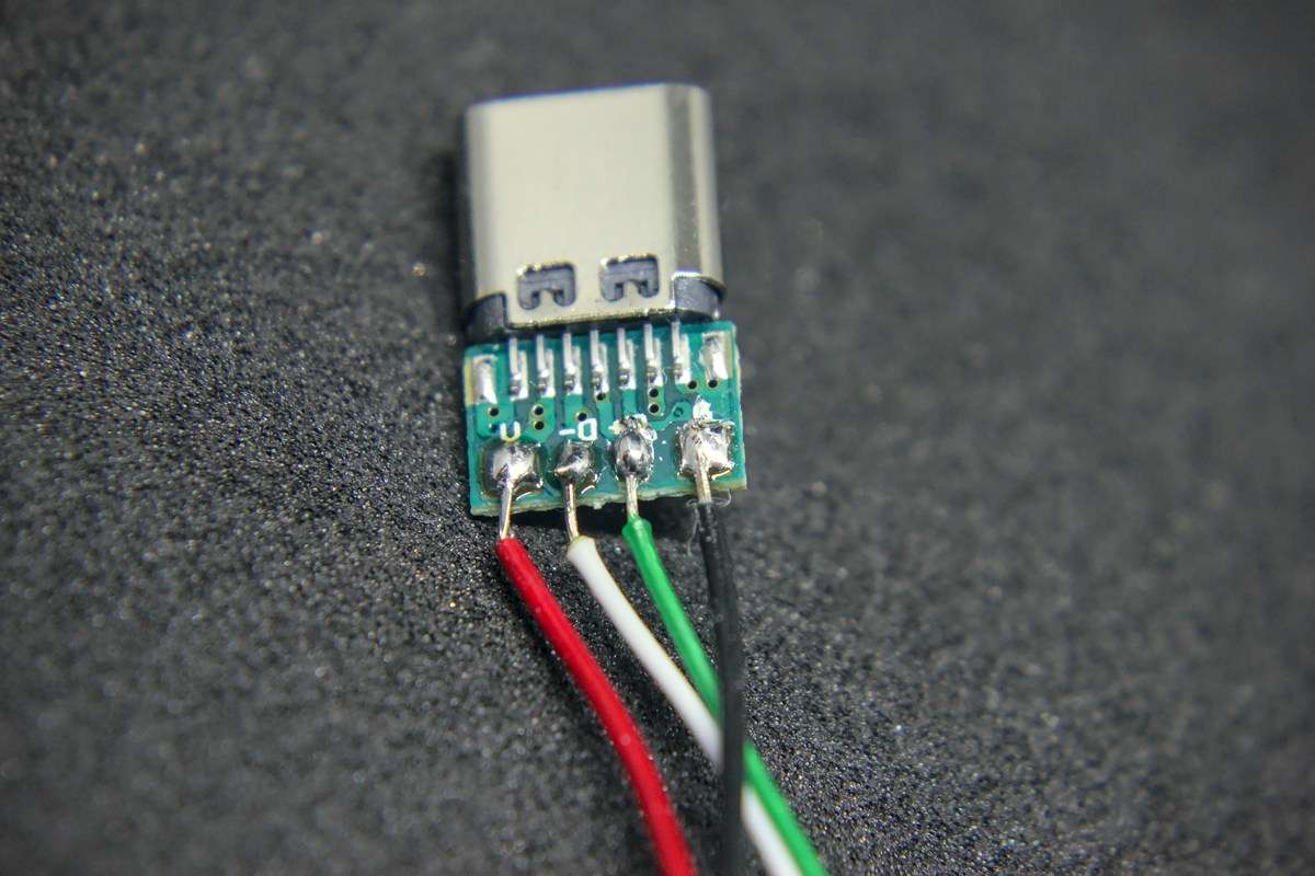
- a female USB Type-C breakout board that exposes the ground (GND), voltage (V), data plus (D+), and data minus (D-) pins (Note: If you plan to use a USB-C to USB-C cable, it should support power delivery.)
Selecting the right breakout board is crucial, as not all boards are suitable for this project. For this modification, search for a board that exposes the GND, V, D+, and D- pins from the female USB Type-C connector. While USB Type-C connectors have many additional pins, only these four are necessary for connecting to a legacy USB device.
If you’re using a USB-A to USB-C cable to connect your device, any board exposing the pertinent pins should suffice. However, if a USB-C to USB-C cable is utilized, the two connected devices must perform a digital “handshake” before the power is delivered from the source device to the sink device. In such cases, two resistors are needed on the breakout board to signal to the source device that our Pi Pico requires the standard 5V.
Initially, I acquired breakout boards without the necessary resistors, which could be an issue for those intending to use USB-C to USB-C connections. Fortunately, since I’m using a USB-A to USB-C cable for development on this Pi Pico, the boards I have will suffice. Nonetheless, I recommend obtaining a breakout board that is properly configured for power delivery. This way, it will be compatible with any USB-C cable or device in the foreseeable future. (I’ve ordered new ones for future projects already)
Connecting the USB Type-C Breakout Board to the Raspberry Pi Pico
When adapting most gadgets, you will need to desolder the existing micro-USB connector to attach the new USB Type-C breakout board. Luckily, with the Raspberry Pi Pico, there’s a more straightforward route.
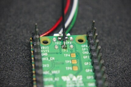
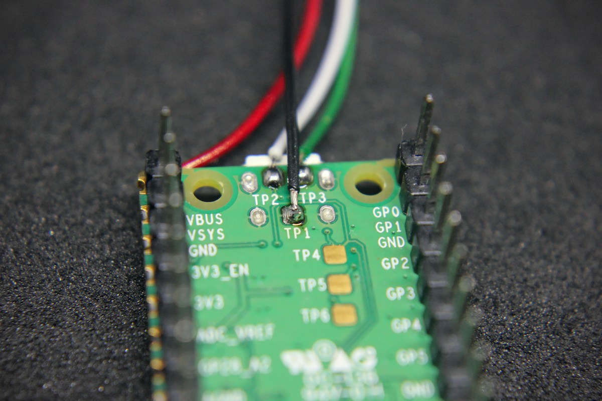
The Pi Pico conveniently provides Test Pads on its underside, labeled TP1 through TP6. These accessible pads grant direct connections to essential lines; ground (TP1), data minus (TP2), and data plus (TP3). The voltage we can provide by soldering to the VBUS pin on the Pi Pico’s GPIO. This hassle-free approach allows us to integrate the USB Type-C breakout board effortlessly, without the need to remove the original micro-USB port.
| Breakout Board Pin | Raspberry Pi Pico Connection | USB Wire Color |
|---|---|---|
| GND | TP1 (Ground) | Black |
| V | VBUS (PIN 40) | Red |
| D+ | TP3 (Data Plus) | Green |
| D- | TP2 (Data Minus) | White |
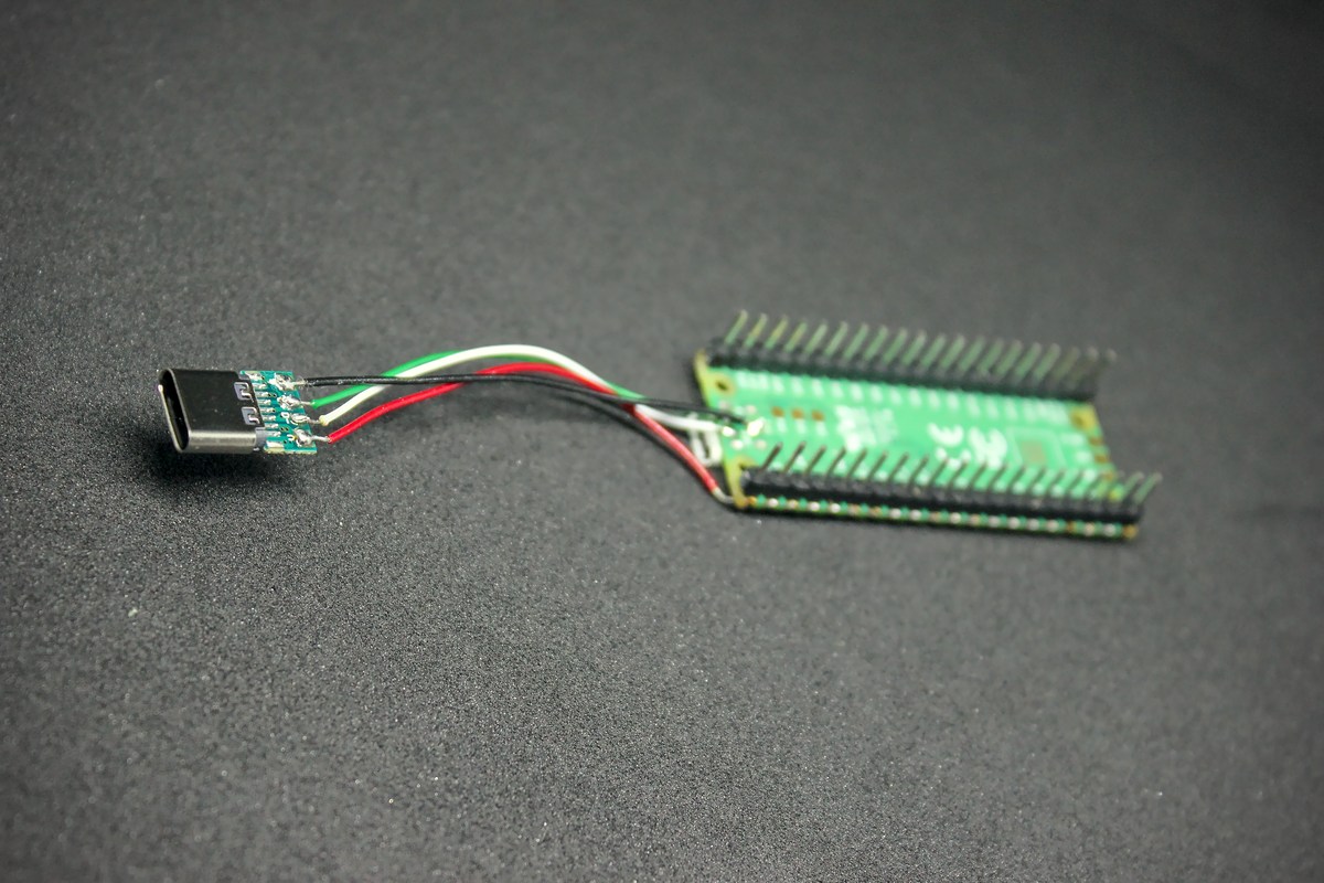
And there you have it! With a few simple connections the Raspberry Pi Pico is transformed into a device with modern USB Type-C compatibility. It’s a straightforward upgrade that adds functionality and convenience with just a few simple soldering steps. Make sure to double-check your connections before testing!
Conclusion
Upgrading a Raspberry Pi Pico to sport a USB Type-C port is a clear example of how a little know-how and soldering can modernize even the simplest of devices. It’s an accessible project that not only enhances connectivity but also serves as a foundation for those looking to delve deeper into the world of DIY electronics. While our example with the Pi Pico was relatively easy, due to the test pad providing easy-access to solder on, other devices might present more of a challenge. Each gadget will have its own set of intricacies and might require additional steps or precautions. This project is a perfect starting point to build your confidence and skills before you graduate to tackling more complex hardware upgrades. Remember to always research thoroughly, take safety precautions, and most importantly, enjoy the process of giving your tech a personal touch. Happy modding!
Disclaimer
Please note that while we strive to provide detailed and clear instructions, we are not responsible for any damage that may occur to your electronics during the modification process. Attempting such modifications requires careful handling and a certain level of proficiency with electronic components and soldering. If you choose to undertake this project, you do so at your own risk. Always ensure you are fully informed and equipped to carry out the task safely before proceeding.
Liked this post ? You can buy me a coffee