A Python powered MacroPad/StreamDeck
with a Raspberry Pi Pico
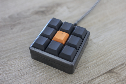
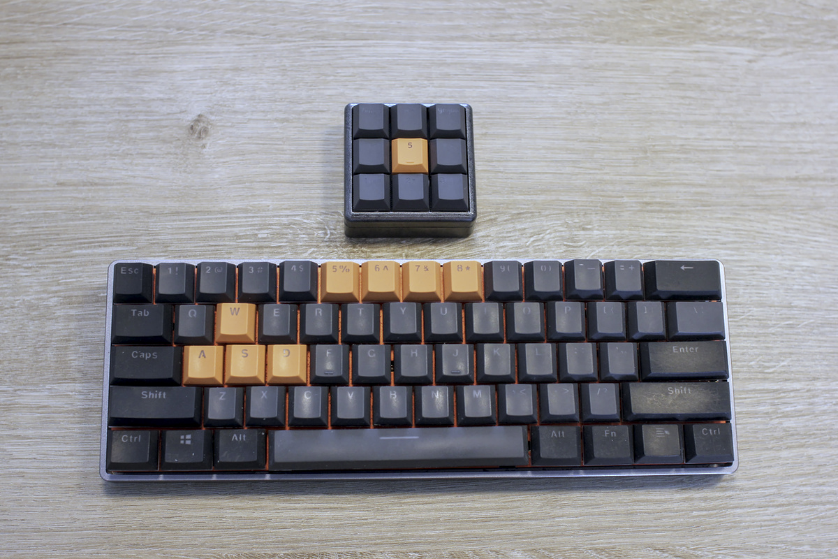
I decided to put left-over parts from my mechanical keyboard and a Raspberry Pi Pico to good use and build a MacroPad. This is a small keypad, where each switch can be programmed with a certain button or combination of buttons to quickly execute often needed shortcuts. Streamers often have this to change scenes or trigger an animation in OBS, hence these are often referred to as StreamDecks.
Requirements
For this project I had a lot of the components at hand. Switches, LEDs and keycaps were left over from my keyboard build. If you do want to do this from scratch, here is a list of items to buy.
- 1x a MacroPad case (3D printed, STL here)
- 1x a Raspberry Pi Pico
- 9x Mechanical keyboard switches (Gateron, Cherry MX, Kailh… should all fit)
- a set of keycaps (e.g. for numpad keys)
- 9x 1.8 mm 2V LEDs (current 15-20 mA) (optional)
- 9x 82 Ohm resistors (optional)
- 1x a switch opener (optional)
- 4x M3 bolts (14-16 mm long, I cut down 20 mm bolts to fit)
- some heat-shrink tubing
- wire, single core and flexible
- soldering equipment
- a third hand tool
- a hot-glue gun
- a USB-micro cable
Designing and printing the case
As there were no 3x3 MacroPad cases that would fit a Raspberry Pi Pico, I mixed two designs using Blender to create a suited case. I started with a design that uses a Pro Micro at the core and replaced the bits that hold the Pro Micro with the inside part from a pico case. In addition, I made the case a bit higher as more wires need to fit inside. The result was a nice case with a spot that holds a Raspberry Pi Pico perfectly. I prefer PETG printed using these settings, but PLA will do just fine as well.
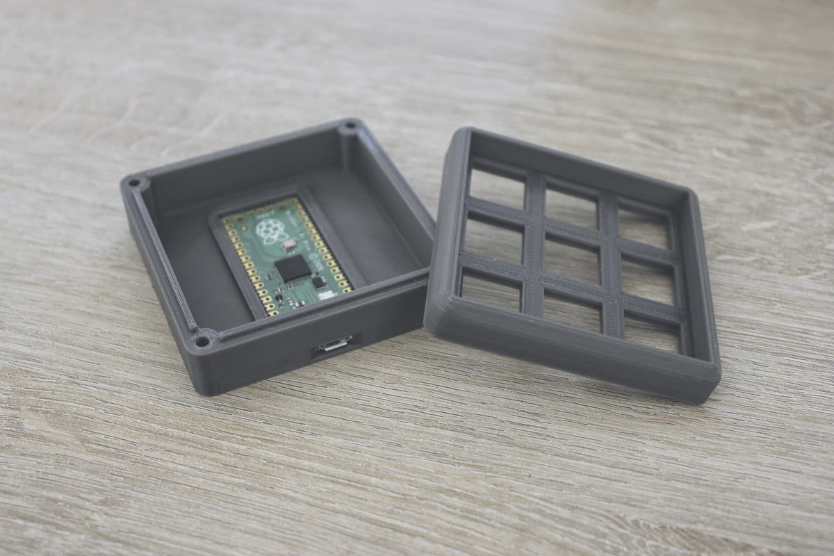
If you want to print this yourself, grab my design from Thingiverse or you download the STL files here directly.
Finishing the case
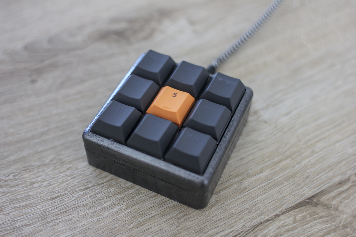
I wanted to match the case with my current keyboard, which has a dark gray anodized aluminium case. To do this, after sanding and priming the case a black base coat was applied. Next, some Vallejo Gun Metal (acrylic paint for miniatures) was applied by dabbing it on with a sponge. Finally, a few layers clear coat were applied so seal the paint and provide a finish that is durable and more pleasant to touch.
Preparing the switches
(If you opt to forgo the LEDs this step can be skipped.)
For this project I used Gateron Green mechanical switches, while these have space to fit a 1.8 mm LED, the switch needs to be opened to install them. This can be done using a special tool, which can be 3D printed. I used this one, which worked quite well. Note that some switches, e.g. Kailh, are open on one end, so LEDs can be fitted without opening the case.
Hand-wiring the switches
First install the switches in the case, the snap in place but pay attention to the orientation. I decided for a North-Facing configuration where the LEDs are located on the upper part of the switch, this looks better with translucent keycaps. A resistor was installed on each switch from the LED’s ground to one pin of the switch (see below). These were then connected together for all nine switches equipped with LEDs and the Pi Pico’s ground. A wire was soldered to the other pins of the switches and LEDs and these all went to their own GPIO pin to ensure all LEDs can be controlled individually and switches can be read directly.
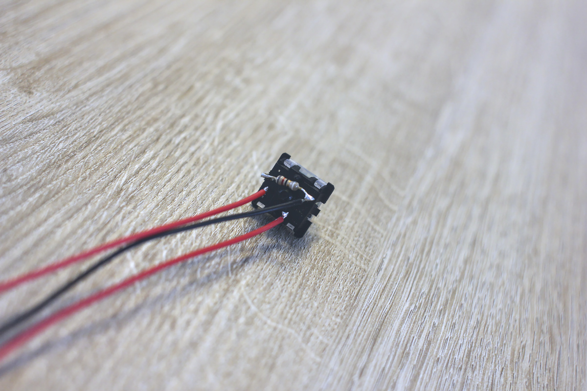
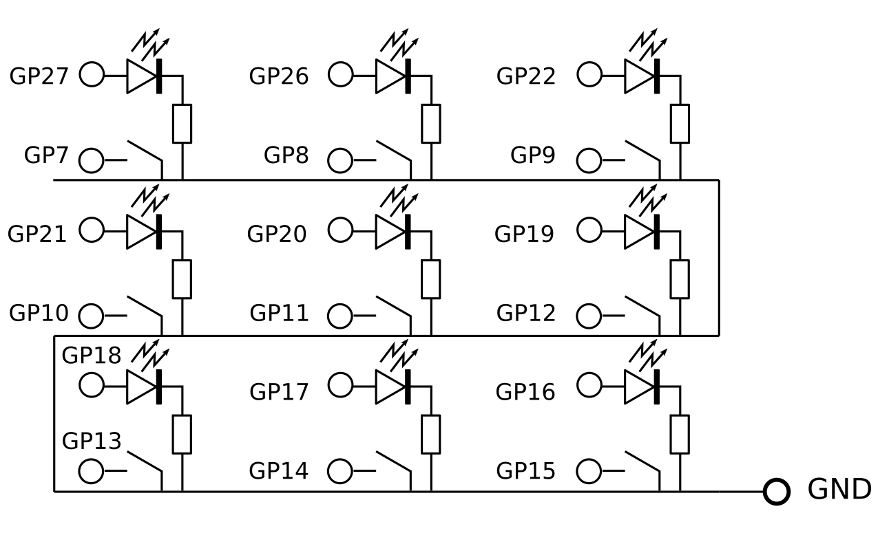
The picture above shows how each resistor was wired up to the ground of the LED and the switch. All grounds were then soldered together with a long wire and connected to the Pico’s GND pad. The other two pins (here shown with red wires) were connected with GPIO pins, the full diagram is shown below.
Preparing the Raspberry Pi Pico
Before any Python code can run, we need to install the correct firmware on the Pico. The Adafruit HID library which makes it possible to emulate keystrokes is only available for CircuitPython only. (I couldn’t find an equivalent for MicroPython) To set everything up I recommend going through a few videos from Novatech Spirit. He has excellent instructions on how to set up the Thonny IDE, CircuitPython and the Adafruit HID library. Another video on his channel explains how to make a simple MacroPad, and the code below is based on this project. However, where he copy-pastes code for each button, here a more elegant solution is included and there are a few additional tricks necessary to get the buttons to works with animated LEDs.
In a nutshell, download the CircuitPython .UF2 file first. Hold the BOOT_SEL button on the Pi Pico when connecting it to the
PC. The Pi will show up as a drive, copy the .UF2 file to this drive, and the device will reboot. Once it shows up again, it will
be mounted as a drive as before but with new files there, download the Adafruit HID code and copy the folder
adafruit_hid to the Pi’s lib folder. The code below should be put in code.py on the Pico.
The code
The code consists of two main parts. The first part, after importing the libraries are configurations, defines which
GPIO pins are connected for LEDs and buttons as well as
which keys we want to map the buttons to. Important is that everything in these lists is in the
correct order. Then the keyboard, buttons and PWM cycles for the LEDs are also initiated. Two arrays, duty_cycles and
last_pressed are created to keep track of each LEDs current brightness and how long it was since a key was last
pressed.
Once the code that tells the microcontroller which hardware is connected and how it needs to listen for button presses and act accordingly. Since CircuitPython doesn’t seem to support multi-threading or interrupts on the Pi Pico, everything has to be done in the main loop. This consists of a few steps that are repeated over and over…
- Check if a button (on the MacroPad) was pressed, and set a value in
last_pressedif necessary and set the button’s LED to full brightness induty_cycles - Emulate button presses as a HID device if required
- Emulate button releases as a HID device if required
- Decrease
last_pressed - Update the LEDs duty cycles and decrease the values in
duty_cylcesto fade them out - Sleep for a minimal amount
import board
import digitalio
import pwmio
import time
import usb_hid
from adafruit_hid.keyboard import Keyboard
from adafruit_hid.keycode import Keycode

# Configuration, which LED pins are used, which buttons, how buttons map to macros
led_pins = [board.GP18,board.GP17,board.GP16,board.GP21,board.GP20,board.GP19, board.GP27, board.GP26,board.GP22]
button_pins = [board.GP13,board.GP14,board.GP15, board.GP10,board.GP11,board.GP12,board.GP7,board.GP8,board.GP9]

button_mapping = [
    [Keycode.LEFT_CONTROL, Keycode.F1],
    [Keycode.LEFT_CONTROL, Keycode.F2],
    [Keycode.LEFT_CONTROL, Keycode.F3],
    [Keycode.LEFT_CONTROL, Keycode.F4],
    [Keycode.LEFT_CONTROL, Keycode.F5],
    [Keycode.LEFT_CONTROL, Keycode.F6],
    [Keycode.LEFT_CONTROL, Keycode.F7],
    [Keycode.LEFT_CONTROL, Keycode.F8],
    [Keycode.LEFT_CONTROL, Keycode.F9]]


keyboard = Keyboard(usb_hid.devices)

# Set up buttons
buttons = [digitalio.DigitalInOut(bp) for bp in button_pins]

for btn in buttons:
    btn.direction = digitalio.Direction.INPUT
    btn.pull = digitalio.Pull.UP

# Set up LEDs
leds = [pwmio.PWMOut(lp, frequency=1000, duty_cycle=0) for lp in led_pins]

# Set Initial Duty Cycles to 0 for each LED
duty_cycles = [0 for _ in led_pins]

# Last Pressed
last_pressed = [0 for _ in button_pins]

while True:
    for ix, btn in enumerate(buttons):
        if not btn.value:
            duty_cycles[ix] = 65025
            last_pressed[ix] = 25 if last_pressed[ix] <= 1 else last_pressed[ix]

    for ix, lp in enumerate(last_pressed):
        if lp == 25:
            # print("button %d pressed" % ix)
            keyboard.press(*button_mapping[ix])

    for ix, lp in enumerate(last_pressed):
        if lp == 1:
            # print("button %d released" % ix)
            keyboard.release(*button_mapping[ix])

    last_pressed = [max(0, lp - 1) for lp in last_pressed]

    for ix, led in enumerate(leds):
        led.duty_cycle = duty_cycles[ix]
        duty_cycles[ix] = max(duty_cycles[ix] - 900, 0)

    time.sleep(0.01)
When using this code, the LED under each button will light up as soon as you press a button and then quickly fade out.
The fade out speed can be changed by changing 900 in duty_cycles[ix] = max(duty_cycles[ix] - 900, 0) to a higher
or lower value to fade quicker or slower respectively.
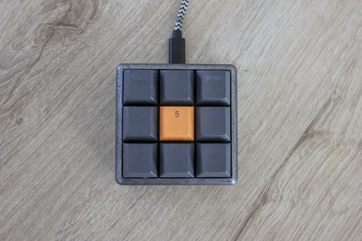
For my setup I’ve linked buttons 1-9 with CTRL+F1 - CTRL+F9 which are common shortcuts in multiple programs (e.g. CTRL+F4 will close the current tab in Chrome, CTRL+F5 is a hard refresh, …) and these can be bound to links on the desktop too. Though ultimately these could be anything, just modify the mapping in the code and done.
Closing the case
Once you are sure everything works, put everything in the case carefully. Soldered joints can be fragile so be gentle with the wiring and make sure not to apply force as this could break connections. You’ll need a few dots of hot glue to keep the Pi Pico in place in the bottom half of the case. Use the M3 bolts to screw the case close. There is no thread, though it should work well enough as the bolt will grab the ridges in the 3D printed holes, just don’t open and close the case more than necessary as this will wear fast.
Conclusion
By 3D printing the case, using spare switches and keycaps this was a pretty cheap project for me and it works quite well. There is little to no lag when pressing a button. It would be cool to make the software more complex. Having multiple configurations and switching between them using combinations of keys could be a nifty feature, but for now nine extra buttons will have to suffice. Something more complex will be for a future post.
Links
Liked this post ? You can buy me a coffee